|
GStarICAD2008 has integrated HPGL/2, OCE, PS/EPS, PDF, EMF/WMF print
drivers, GstarCAD2009 has more strong and perfect print functions
1. HDI upgrades to 3.0 version
Re-developer can customize print interface in GstarCAD2009.
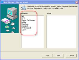
2. Cooperate with Canon to develop Canon series print drivers |
|
 |
|
3. Add DWF virtual print driver and realize the web publish function.
Different from the direct DWF export before, this published file
contains all the DWF information and users can export DWF file according
to selected area
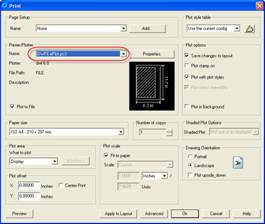
The process of creating DWF file
Select "DWF6 ePlot.pc3" printer, other steps are same to the normal
print. |
|
 |
|
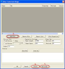
4. Frame Auto Range
Many drawings can be arranged automatically through software
calculation. It not only can enhance print efficiency but also can save
paper.
Command: ZDPT
Menu: Express>Automatic row diagram
Operation Steps:
(1) If you use this function at first time, you should do some settings
at "Option" item
(2) Select the arranged file from "add file" item
(3) After selecting the arranged file you can "tryout" these files, and
preview the arranged effect. |
|
 |
|
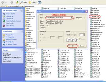
5. PLT output tool
Users can send PLT files to printer to print.
Operation Steps:
1) Right-click GStarCAD icon>Properties>Find Target
2) Select PrintPlt.exe in the dialog box |
|
 |
|
3) Double-click the PrintPlt.exe file, then the "Print" dialog box will
be displayed,
in the dialog box you can select printer or do some settings.
4) Click OK button, the "Open" dialog box is displayed, you can select
the printed file. |
|
Perfect Management Functions: |
|
1. New Drawing Wizard
User can select modes and also can select required template files
Command: New
Menu: File>New
When the system variable "startup" is on, click "new" icon the following
dialog box will emerge
1) User can create a new drawing according to English or Metric |
|
 |
|
2) User can create a new drawing according to the existing template |
|
 |
|
3) User can create a new drawing according to use wizard |
|
 |
|
2. Layer Translator
Command: Laytrans
Changes a drawing's layers to layer standards you specify.
In the Layer Translator, you specify the layers in the current drawing
that you want to translate, and the layers to translate them to. |
|
 |
|
Translate From: Specify the layers to be translated in the current
drawing.
Selection Filter: Specify layers to be selected in the Translate From
list
Translate To: List the layers you can translate the current drawing's
layers to.
Load: Load layers in the "Translate To" list using a drawing, drawing
template, or standards file that you specify.
New: Define a new layer to be shown in the Translate To list for
translation.
Map: List each layer to be translated and the properties to which the
layer will be converted.
Settings: Open the Settings dialog box, where you can customize the
process of layer translation.
Translate: Start layer translation of the layers you have mapped.
3. View Manager
User can name many views and switch quickly between each views, It is
helpful to reduce many unnecessary view adjust operation
Command: View
Menu: View> Named Views
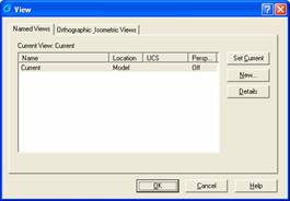
There are two tabs in this dialog box, named view tab and orthographic
isometric view tab.
1) Named Views Tab |
|
 |
|
Set Current: Restore the selected view.
New: Create a named view. And "new view" dialog box will emerge
Details: Display "detail of view" dialog box
2) Orthographic Isometric View Tab |
|
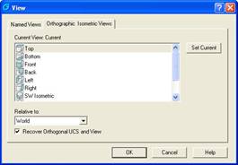 |
Set Current: Restore the selected view.
Current View: Display the name of current view
Relative to: Specify the base coordinate system which is used to define
the orthographic view, the WCS is the default base coordinate system.
Recover Orthographic UCS and View: Restore the relative UCS when set
orthographic view as current.
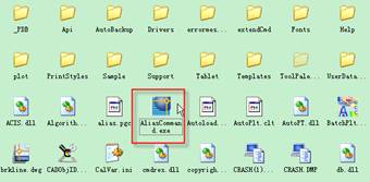
4. Alias Edit
GstarCAD 2009 provides executable file "aliascommand.exe". User can
modify alias and need not to enable GstarCAD. In GstarCAD 2009 user can
customize system command such as: run,cmd,start and etc.
Command: Aliasedit
Menu: Express>Tools>Order any nickname editor
1) The executable file "aliascommand.exe" in installation catalog |
|
 |
|
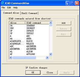
2) The command alias dialog box in GStarCAD2009 |
|
 |
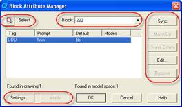
5. Block Attribute Manager
Manages the attributes for a selected block definition, preview
modification automatically, it is convenient to modify attribute block
in quantity.
Command: Battman |
|
 |
|
Select: Allow you to use your pointing device to select a block from the
drawing area.
Block: List all block definitions in the current drawing that have
attributes. Sync: Update all instances of the selected block with the
attribute properties currently defined.
Move Up: Move the selected attribute tag earlier in the prompt sequence.
Move Down: Move the selected attribute tag later in the prompt sequence.
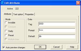
Edit: Opens the "Edit Attribute" dialog box, where you can modify
attribute properties. |
|
 |
|
Remove: Remove the selected attribute from the block definition.
Settings: Opens the "Block Attribute Settings" dialog box, where you can
customize how attribute information is listed in the Block Attribute
Manager.
Apply: Apply the changes you made, but leave the dialog box open.
6. Block Count
User can know the block name and the number of inserted block in the
selected object. It is compatible with the Bcount command in AutoCAD.
Command: Bcount
7. The Upgrade of Design Center and Tool Palettes
The blocks in design center can be dragged to drawing area, the blocks
in drawing area can be dragged to tool palettes too. The input and
output function of tool palettes is helpful to share and reuse. |
|
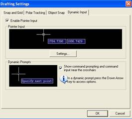 |
Enable Pointer Input: turn on or off pointer input
Settings: Display "Pointer Input Settings" dialog box
2. The Enhancement of Selection Function
Selection box will be displayed dynamically and transparently, the two
selection mode "window" and "crossing" will be differentiated by color.
The two different effects are below:
The display of window selection: |
|
 |
|
The display of crossing selection: |
|
 |
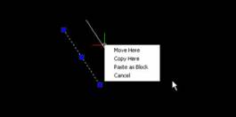
3. The Drag of Right Mouse Key
Use right mouse key to drag after selecting entity, the shortcut menu
will be displayed it is another operation mode. |
|
 |
|
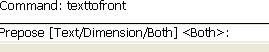
4. Text to Front
Bring text and dimensions in front of all other objects in the drawing
Command: TEXTTOFRONT
Menu: Tools>Draw order>Bring text and dimensions to front
Operation steps:
1) Execute command
2) Input the object type of being to front |
|
 |
|
The effect before input |
|
|
|
 |
|
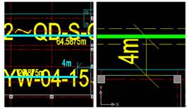
If input Text, and all the text will be to front, the effect is below |
|
 |
|
If input Dimension, and all the dimensions will be to front, the effect
is below |
|
 |
|
If input both, and all the text and dimensions will be to front, the
effect is below |
|
 |
|
5. Quick Calculator
Evaluate mathematical and geometric expressions. Different from common
calculator, quick calculator is an expression generator. In order to get
more flexibility, quick calculator will not give the answer immediately
but let user input a editable expression then press Enter or equal sign
to get the result. In addition, user can find the inputted expression
from history record, and modify it or recalculate.
Open and close quick calculator
Command: quickcalc and qcclose
Menu: tools>Palettes>Quickcalc
Shortcut key: CTRL+8
6. HCCAD Tools
HCCAD Tools integrated many convenient drawing tools, user can use
GStarCAD platform software to finish many professional design such as
pipeline design.
1) Drawing Scale
Command:SASCL
Set drawing scale before starting to draw, software will adjust the
scale automatically when you use other tools such as modifying
lineweight.
2) Control Parameters--Cross to break width
Command:CBKWID
Set the width of fast tripping cross, about "the fast tripping cross" we
will introduce it later
3) Rotate Cursor
Command:RTCUR
Set the cursor to the angle that you want. You can choose 0 degree or 45
degree which have been set; you also can choose "Alongside Line" to
select a line, the cursor angle will become corresponding with the line;
If you select "Real Time Rotate" and it seems that you enter into a
little play, you can use AWSD four key to control the rotate of the
cursor till you press Enter to finish it
4) Line Such as Chord
Command:SALPL
It is very convenient to use "Line such as chord" function to draw
isometric drawing.
Software will prompt you to input lineweight value, you can set the
value according your need, then start to draw your entity, the graphic
way is the same with drawing common multiline, software supplies the
usually used angle 0 degree and 45 degree, you can set the angle value
by yourself, it will feel the drawing process is fast and easy. The
sample drawing is below: |
|
 |
|
5)
Extension
Command:ETT
The extension location can be displayed in real-time until to the final
location
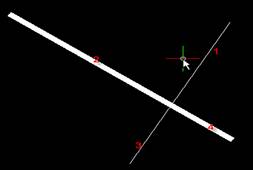
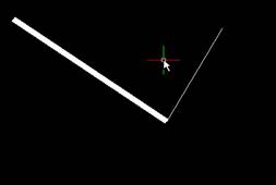
6) Normal Connect
Command:GXFILT
This function is similar with 0 distance chamfer. If there are two
intersectant line or pline, the selected part will be retained and other
part will be cut |
|
 |
|
Select 1 and 2 to use "normal
connect", and so 3 and 4 will be cut, the effect is below |
|
 |
|
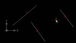
7)
Flex connect
Command:GXFSS
As long as two lines or pline are not parallel, they can realize "flex
connect", this function will make selected line extend to the location
where it intersect with the target line or where it intersect with the
extension line of the target line. The sample picture is below:
Now use 1 with 2 and 1 with 3 to use this function separately |
|
 |
|
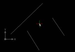
The situation before "Flex
connect" |
|
 |
|
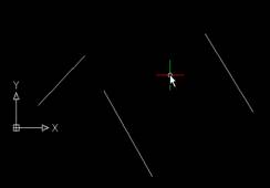
1 with 2 to use the function |
|
 |
|
1with3 to
use the function8) Super Fillet
Command:SFILLET
Why we can this function "Super fillet"? because this function not only
can finish the usual fillet operation but also can unify the two lines'
information such as layer,color,line type and etc, the unified standard
is according to the firstly selected line. |
|
 |
|
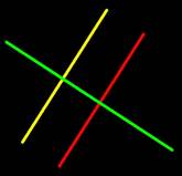
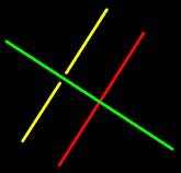
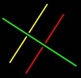
In this
drawing, these two lines have different color and line type, now we use
super fillet function to theme.
Please enter the Fillet radius<0>:
The software will prompt you after you input the radius
Please select the first line segment:
The selected first lien will determine the layer?color and line type of
filleted two lines, here we select the green lien as the first line,
then select the yellow line to do super fillet, the result is below: |
|
 |
|
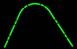
9) Modify
linewidth
Command:LCW
Change the linewidth of specified pline, if you select a line and
software will translate this line into pline and set linewidth
automatically for it. It is very convenient to edit linewidth.
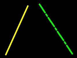
10) Cross to break soon
Command:CBK
We often need to break many lines when drawing, but it is very
unconvenient to do this by hand. This aim can be easily finished by this
function supplied by GstarCAD
Software will prompt you to select a line which is to break other lines
namely the cover line segment then you can select the breaking lines.
Use the green line as the cover line to break the red line and yellow
line. The effect is below: |
|
 |
 |
 |
|
11) Modify
Text
Command:EDTXT
Supply some functions to single text such as: height?text width
factor?angle?obliquing angle
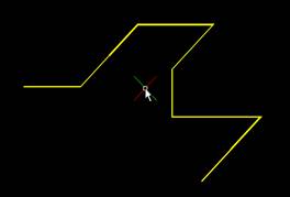
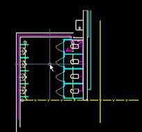
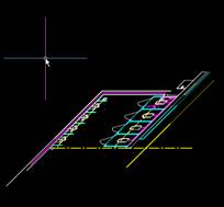
12) Super Axonometric
Command:ZC
It is a very helpful function, you can translate plan drawing into
isometric drawing easily with it.
The operation way is very easy, you should select the translated drawing
at first, then set the axonometric angle, at last press Enter to finish
your operation. |
|
 |
 |
|
Before translation |
After translation |
|
Strong Re-development Environment(In Development Version): |
|
GstarCAD 2009 Development Version supports all the re-development
interfaces of AutoCAD.
1. GRX Programming
Interface
GRX programming interface is
provided which is compatible with ARX, based on C++, object-oriented
re-development environment and application interface.
GstarCAD2009 supports all the development interface: AutoLISP, Visual
LISP(including IDE), SDS(ADS), VBA, GRX(ARX)
2. VBA development
interface
Microsoft VBA(Visual Basic for Application) is an object-oriented
programming environment designed to provide rich development
capabilities, which is a strong development tool. GstarCAD2009 also
integrates VBA development tool, and provides ActiveX Automation
suitable to VBA development
3. GstarCAD Visual
LISP IDE
GstarCAD2009 provides the customers who are accustomed to using LISP
with a visual development interface and environment. The VLISP
integrated development environment (IDE) provides features to help ease
the tasks of source-code creation and modification, program testing, and
debugging. In addition, VLISP provides a vehicle for delivering
standalone applications written in AutoLISP. |
|
Go to
Download |